Sorry, Web Serial is not supported on this browser and is needed to connect to the Pico.
Web Serial is available in Chrome 89 or later on all desktop platforms (Windows, macOS, Linux or Chrome OS).
Firmware: not connected
Analog
0.000
Digital
User Guide
Pre-requisites
- Chrome ver 89 or later under Windows, macOS, Linux or Chrome OS (Chromebooks). Windows users can also use Edge browser ver 89 or later.
- Raspberry Pico with pre-soldered headers. Soldering the headers yourself is not recommended unless you have experience or under the guidance of an experienced instructor
- USB cable
- Breadboard and wires
- Digital Logic ICs that are in DIP (Dual Inline Package with pins to stick into the holes in the breadboard). Since the Pico supplies only 3.3V VCC, we recommend the HC series (they operate from 2V minimum). You can also choose other digital IC families that operate at 3.3V supply in DIP and from distributors most convenient for you.
- If you have never breadboarded before, practice on our virtual breadboard first
Getting Started
- Download the firmware emant47v1.uf2 for the Pico
- Program the Pico
- Press the BOOTSEL button and hold it while you connect the other end of the micro USB cable to your computer. The Pico will now appear as a drive.
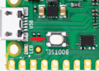
- Drag and drop the downloaded firmware into the drive. The Pico will reboot as a USB serial device
- Press the BOOTSEL button and hold it while you connect the other end of the micro USB cable to your computer. The Pico will now appear as a drive.
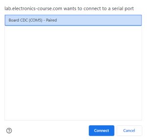
- Click CONNECT and choose the Pico. On Windows, the device appears as Board CDC. On Linux, MacOS and ChromeOS, it is Pico. The Pico is now a digital trainer.
- Connect the 3.3V VCC and GND to your breadboard. You need only to connect one GND but connecting all four will prevent you from accidently connecting them as Switches or LEDs.
- Wire your circuit to the Switches (SW7 to SW0) and LEDs (D7 to D0) according to the pinout of the Pico shown on this page. Don't forget to connect the 3.3V VCC and GND to your ICs
Example
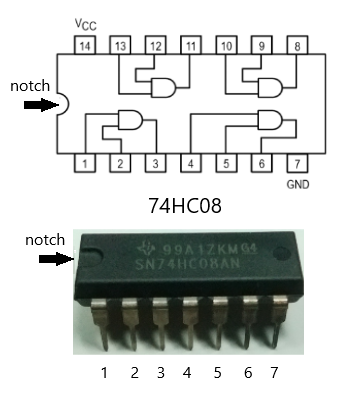
We will test a 2 input AND gate using the 74HC08 in DIP. The notch on the package is used to locate pin 1. When the notch is on the left, pin 1 is the bottom left corner of the device.
We will make the following connections
- one input of the AND gate (pin 1) to SW0 of the Pico (yellow wire)
- the other input of the AND gate (pin 2) to SW1 of the Pico (brown wire)
- the output of the AND gate (pin 3) to D0 of the Pico (green wire)
- 3.3V Vcc to pin 14 of the IC (red wire)
- GND to pin 7 of the IC (black wire)
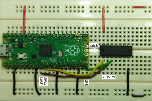
Connect to the Pico, press the buttons SW0 and SW1 and observe D0. As expected, D0 will light up only with both SW0 and SW1 are on.